The Working
Principle
Notice our technical contributions
reviewed by expert editing and
retrace our innovation's relevance.
Read on Elektronikpraxis -online and
seize our English translation given below.
Our Translations* provided:

Defects in solder joints: In many cases it is not known how exactly these defects occur.
How do defects occur in solder joints ?
28.11.19 | Author / Editor: Landulf Martin Skoda / Dr. Anna-Lena Gutberlet
This first part of an empirical study covers the development of defects in solder joints during hand soldering with Sn63Pb37 and reveals typical causes.
There is a high degree of uncertainty among experts as to the origin of the various types of defects in solder joints. Corresponding knowledge about this can only be gained if complex soldering is part of daily operations.
This first part of a soldering study looks at the development of defects in solder joints and shows typical causes.
Contrary to the assumption that a solder joint made of eutectic Sn63Pb37 initially solidifies abruptly, other things can be observed during soldering operations under 10x magnification.
The solidification and formation of the solder does not occur at a certain point in time, but within a period of time and in specific areas.
From this it can be concluded that although eutectic solder in itself solidifies abruptly, an entire solder joint of Sn63Pb37 does not.
The eutectic property of Sn63Pb37 stands in the way of the desired homogeneous formation of solder joints, in so far as the solder cannot align and arrange itself analogously to the respective unconstrained heat dissipation of individual components.
The quality of a solder joint is not only reflected in the ability to allow solder flow, but also - and much more so - in the inconsistent heat loss across the individual components.
Using the example of a classic THT soldering - pin, bonding continuity, solder composition, soldering temperature and optionally an additional heat supply can be used to provide
an overview of the reference complex that can hardly be grasped.
Based on the contrasting nature of heat dissipation (divergence) within a solder joint and its different characteristics, the different types of defects can be explained, successfully eliminated and also avoided in advance by means of simple technical approaches.
Even if the complexity in the field of SMT is significantly lower, the principle of operation shown can also be transferred and applied here.
Aspects relevant to the formation of the solder
Thermal expansion / Solder flow direction: Due to the higher expansion of the solder under heating, a suction effect occurs, through which colder, but already fluid solder is pulled in the direction of the heat source. Free-flowing solder is always oriented towards the heat source or the warmest area (solder flow direction). This observation must not be limited to visually detectable processes.
Even within a complex solder joint, fluid solder permanently expands in the direction of the heat source (expansion) or in the direction of heat dissipation (shrinkage).
This fact shows up as a basic problem for the emergence of the defects. Only when the soldering tip is removed (heat source) is the expansion or flow direction of the solder given free rein, so that divergences of different shades are created. This concept opens up new challenges and possibilities for any kind of fabrication of solder joints of the highest quality.
Verification by means of solder ball formation
In order to prove the occurrence of relevant failures due to divergences, the focus should be directed in the opposite direction to the formation of a solder ball:
A liquefied quantity of tin-lead solder (e.g. adhering to a soldering tip) forms a ball in the open. As far as this ball cools down before an impact, the spherical shape remains.
In itself, a solder ball can be regarded as a solder of the highest quality, as there are no distortions in the solder.
If the surface tension is taken into account, ball formation can be explained, but at the same time it should be noted that the heat dissipation during this process is balanced uniformly in all directions (no mass connection, no heat input) (Figure 1).
Not least because of the absence of different expansions and therefore also the absence of divergence, no differences in stress occur within this process, whereby a uniform surface tension and the formation of balls is ultimately enabled.

Figure 1: A solder ball can be indicative for a soldering of highest quality as there are no distortions within the solder.
The convergence phase is reached when the heat shrinkage occurs equally over each component of the soldered joint through appropriate action. Such a cooling would correspond approximately to that which leads to the formation of a solder ball.
For a faultless soldering result, the achievement of the convergence phase would be desirable. However, the flat wetting angle required for high quality solder joints cannot form out of this, as the expansion of the solder results in convex shape formation. Nevertheless, the understanding of the convergence phase is a central point of reference for soldering operations.
Relative heat saturation: Since the strength of the heat shrinkage is a deciding factor in the occurrence of defects, the heat saturation of a connection must be considered – this is relative to the demand of the soldered joint. The higher the heat saturation of a connection turns out, the lower the shrinkage within the solder.
If a fault is reworked under the same conditions (base temperature, soldering temperature, soldering position, soldering time) after a defect has occurred, the result is almost identical. Inclusions, insufficient wetting, vibrations or similar are therefore not to be given priority as the cause, as the variability of such influences is also higher than the soldering conditions themselves.
Failure as a result of divergence
Taking the above aspects into consideration, a disruption can be represented as the result of a divergence. The various forms of characteristics are now listed below.

Figure 2: After a heavy solder flow a sagging occurs mainly on the soldering side, which implies a large grounding connection of the solder joint.
After heavy solder flow a subsidence occurs mainly on the soldering side, which presupposes a large grounding connection of the solder joint.
The disproportionate dimensioning and positioning of the pin causes the strong expansion of the solder towards the inside of the gap. The difference in direction of the expansions (divergence) leads towards one point. The convergence phase is fallen short of (Fig. 2). The arrangement of the grounding connections also has a higher regularity within the through contact, so that the shrinkage only converges from the point in question.
If the additional heating is set too high, subsidence will occur even with suitable pin thicknesses, and the printed circuit board will experience too much heat saturation after the soldering tip is removed.
The solder then no longer shrinks in the direction of heat dissipation, but rather expands in the direction of the heat source (e.g. heating plate). Due to the lack of heat dissipation, this type of subsidence occurs in conjunction with granulation. The convergence phase is then exceeded.
Separation lines are created in solder joints on the solder side with thicker pin diameters.
It is more meaningful to look at the cooling of the solder rather than the expansion. Due to the higher heat dissipation of the pin, the area above the separating line is the area that cools down prematurely, as the amount of solder is also lowest here.
The convergence phase is only slightly less than this (Figure 3). The divergence runs on one level through the solder meniscus. The cooling of two areas is uniform over a certain length in the solder joint.
A dividing line is equivalent to a so-called melting line, which occurs when the solder joint has not been completely melted during rework. This means that even with separation lines, there are two different levels of cooling.

Figure 3: Separation lines are created in solder joints with thicker pin diameters on the soldering side.
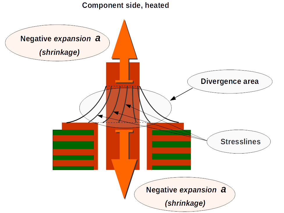
Figure 4: So-called stresslines always form vertically an usually on the component side.
So-called stresslines always form vertically and usually on the component side. Due to a large mass bonding of the connection, and now also of the component, additional heating is used (Fig. 4).
After increasing the heat saturation, the connection and the component act as heat source when the soldering tip is removed. The solder is stretched equally in both directions, with the entire meniscus appearing as a divergence area. The convergence phase is greatly exceeded.
One can imagine how a wide rubber band casts wrinkles when it is stretched equally in both directions at certain points. A supposed "overheating" of the solder (stress) should be avoided, since Sn63Pb37 can still assume an excellent shape even after high heating.
A granular solder joint occurs primarily on the solder side after a noticeably light solder flow. It implies a low grounding connection of the through connection.
At the same time, it occurs in connection with insufficient pin thickness, so that heat dissipation via the pin is not relevant (Figure 5). Due to too high heat saturation of the connection, the entire solder meniscus also shows as a divergence area.
If the heat dissipation does not take place, the solder is in a state of thermal limbo. The persistence of the solder in the direction of the lowest heat dissipation ("expansion") opposes the shrinkage forces which are too low but still effective.
The resulting rough surface can be interpreted as the largest possible accumulation of cavities in a solder joint. Under supplementary heating of the solder joint, granulations can also form when working with thicker pin diameters.

Figure 5: A granular solder joint occurs primarily on the solder-side after a noticeably light solder flow.

Figure 6: Holes can occur in solder joints due to a large heat dissipation via the pin and on one side of the through connection.
Holes can occur in solder joints due to a large heat dissipation via the pin and on one side of the contact surface.
The conditions for this are increased when working with a stranded wire, for example: More heat can be absorbed and dissipated by a larger surface or jacket area within a stranded wire. The shrinkage of the solder occurs horizontally along the entire length of the interconnect.
The convergence phase is greatly reduced (Fig. 6).The consideration of dewetting is inconclusive if the solder is not interlaced. Any increasing heating below the convergence phase increases the non-wetting of the solder.
There is a likelihood of mistaking hole formation due to thermal influence with the inclusion of foreign substances. In this case, it is useful to note that not only the solder but also other substances in the fluid state expand in the direction of the greater heat. Foreign substances are displaced or flushed out by adequate handling of the heat.
Irrespective of the process, the success of a soldering operation depends on the heat dissipation characteristics of a soldered joint. With regard to the high complexity of printed circuit boards, the solution to this problem seems vague. However, this is the subject of part 2 of this study, which will be published soon.
How can defects in solder joints be prevented ?
09.01.20 | Author / Editor: Landulf Martin Skoda / Dr. Anna-Lena Gutberlet
The solution to this question is amazingly simple in its basic features: divergences must be avoided, and the heat dissipation behaviour of a solder joint must be managed operationally.
To avoid a defect, it is necessary to prevent the occurrence of a divergence and to control the heat dissipation behaviour of a solder joint operationally by controlling the direction of cooling.

Figure 1: Source- and target side of a soldered joint using the common method.
First of all, the conditions for solder ball formation serve as a starting point. The heat saturation of the components should therefore be such that the convergence phase is reached and the heat dissipation is uniform in all directions.
It is therefore appropriate to use an additional heat supply in the case of subsidence (Fig. 1), separation lines and hole formation in order to reduce heat shrinkage via the connection. On the other hand, granulation would be counteracted by a significant reduction in heat saturation.
In the case of stresslines, a reduction of the additional heating is required in order not to exceed the convergence phase.
With regard to the negligible calculability, however, working with the convergence phase is hardly practicable.
Also the tendency of the solder towards an undesirable convex shape requires an alternative approach for the production of high quality and trouble-free solder joints.
How to mould the solder into shape
Convergence does not occur exclusively when cooling is equally distributed in all directions, but also when it occurs in a single or dominant direction. Just as the cooling is ametric and divergent when the soldering tip is removed, the cooling should now be driven in a specific direction by appropriate handling of the soldering tip.
The soldering tip, as the permanently warmest area, is guided out of the soldering point in a controlled manner so that the cooling of the solder converges towards the soldering tip. Such a procedure can be described as “Heat-lifting”.
Regardless of the requirements of a solder joint, a simple layout concept therefore opens up the possibility of producing optimum solder joints in a highly controlled and effective manner with greatly increased reproducibility. In addition to using a soldering iron, other processes using a directed heat source, such as laser or light beam soldering, are also suitable for this purpose.
Even before the layout concept is discussed, an optional variant for heat-lifting is to be indicated, in which the operational requirements are also significantly more demanding.

Figure 2: Convergent cooling can be initiated via the adhesive force of the solder at the soldering tip.
Heat-lifting (Solder-affinity): For extraction of the soldering tip, the properties (flow direction / surface tension) of the solder itself can be used to take control of the cooling process (Fig. 2). It is significant for success to maximize the distance e’ between the soldering tip and the soldering joint when solder is adhering. After the solder has passed through, cooling of the solder is therefore initiated from the component side and proceeds convergently in the direction of the soldering tip.
The timing of the removal of the soldering tip must be in keeping with the soldering conditions. If the tip is removed prematurely, the convergence effect is absent, whereas delayed removal causes unwanted deformation of the solder. This problem is the greater challenge, since it is difficult to determine the parameters for the removal time.
For automated processes, such as robotic soldering, these parameters could, as expected, only be determined individually for each soldering point, according to the respective requirements, at great economic expense. In this respect, this variant is a suboptimal alternative with hardly reproducible results in the case of too little working space for the layout concept.
The convergence pad (layout concept):
A straightforward modification of the layout of common solder pads in the form of a dimensioned, web-like expansion (Fig. 3) opens up the possibility of carrying out heat-lifting in a highly controlled, highly accurate and effective manner.
With a recommended minimum dimension of the expansion of the pad (length ±0.75 mm / width ±0.2 mm), the requirement for available space with common dimensions is readily compatible.
Compared to, for example, thermal pads or short tracks to vias, measuring points or other tracks, the web-like expansion of the convergence pad has no conductive function.
This makes planning during the layout process comparatively uncomplicated, and subsequent implementation is also straightforward. A patent application is pending here (DE 10 2019 131 950.1).

Figure 3: Prototypes of Convergence-Pads for
THT processes (top) and SMT processes (bottom).

Figure 4: Heat-Lifting can be carried out reliably via the web-like expansion of the Convergence Pad
Heat-Lifting (Pad-affinity): On a convergence pad, the soldering tip can now be guided out of the soldering joint independently of the properties of the solder and free of any special manual soldering skills (Fig. 4).
If the amount of solder is handled correctly, this technique also serves to form excellent wetting angles (Fig. 5).
If necessary, residues can be extracted in a controlled manner without creating melting lines in the relevant area. This process step is also favoured by the narrowness of the expansion, as the heat transfer from the expansion into the actual dissolving point is low.
In contrast to the solder-affinity variant, only an early extraction point can negatively influence the result in the relevant area.

Figure 5: Source and target side of a soldered joint using Heat-Lifting with Convergence Pad.
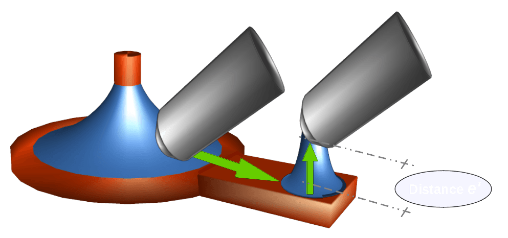
Figure 6: The tolerance during Heat-Lifting is high without adversely affecting the soldered joint itself.
Heat-Lifting (combined): Finally, the convergence pad also increases the flexibility in the operational process. By using additional heat and, if the soldering temperature is set too high, the desired cooling in the course of heat-lifting may not occur.
In order to ensure the convergence effect, the distance to the solder joint itself can now be increased after reaching the edge of the expansion (Figure 6). The handling of the soldering tip then corresponds to that of the optional or solder-affinity variant (Figure 2).
A desired, convergent cooling can now be initiated over a sufficient distance e'. Any deformation of the solder residue, due to delayed removal, no longer affects the result in the respective area.
This combined method can be used as a mandatory method, especially for automated processes, to reduce the determination of the parameters to a minimum.
Note: In the course of heat-lifting during soldering operations, in addition to the visually detectable progress of the solidification beforehand (under a magnification of about 25 times), a definite flow can be detected within the solder, which runs in the direction of the soldering tip.
The temperature used here is high in relation to the demands of the soldered joint. The flow velocity decreases with increasing distance of the soldering tip from the respective quantity of solder (heat-lifting) until the solidification of the solder begins in the same direction.
Increased consistency of soldering results
The independence of the heat dissipation
behaviour of a solder joint gained by the convergence pad increases the reproducibility of the soldering result considerably.
Deviations with regard to the variable parameters also during manual soldering (soldering duration, determination of an additional heating, soldering position, deviating heat transfer by individual approach of the soldering tip, dosing of solder and flux, ...) can be compensated for.
In addition to the possibility of gentle heating of the printed circuit board and component via the web-like expansion, the intended removal of the heat source is gentle on sensitive structures of the component and printed circuit board with regard to their cooling-down.
Creating convergence by using the convergence pad is not limited to soldering iron processes due to its nature.
Those soldering methods which provide for selective heating, as is the case with radiation soldering methods, can be considered here, provided that the orientation of the heat source is flexible enough.
A distance e' (Fig. 6) would be equivalent to a reduction in radiation intensity. The convergence pad thus opens up an important step towards a zero-error strategy, especially for automated processes with directed heat sources.
Reflow soldering and other processes
For other processes, where the full-surface simultaneous heating of printed circuit boards is planned, further approaches to improve the quality of solder joints can be found on the basis of the first part (published in issue 23/2019) of this study. The full-surface heating here greatly reduces the heat dissipation from a solder joint, so that granulation primarily occurs in conjunction with extreme wetting angles.

Figure 7: The use of templates in reflow processes is intended to compensate for the lack of heat dissipation.
One approach to solving this problem is the use of templates. From the templates already available for solder paste printing, variations can be created which are applied to the board after or, if necessary, before assembly (Figure 7).
The modification envisages that in addition to the soldering surfaces, the components are now also excluded. The material used should shield or insulate the board as much as possible from the heat used, so that heat can be dissipated into the board.
In order to improve the heat transfer to the solder joints, a chamfering of the upper edges could be considered for modified templates of special thickness. However, no experience reports are available to this study.
A new expression for new approaches
On the basis of this study, the conclusions of which have been drawn empirically, it appears that a new expression for the field of electronics manufacturing is about to be coined. In the broadest sense, heat-lifting is a soldering profile that takes into account not only a cooling rate but also a cooling direction. In order not to limit itself to soldering iron or other processes with directed heat sources, heat-lifting can ideally be seen as a first category of "Operative Divergency Clearance" (ODC).
This concept generally expresses the fact that divergences in solder joints must be eliminated operationally - i.e. in the continuous heat process - by allocating a clear direction to the cooling of the solder. An existing soldering profile can, to a large extent, provide an average value in relation to the diversity of solder joints and components. For this reason, no further approaches for ODCs are available for the time being, for example for reflow processes, with the exception of the use of templates (Fig. 7), in order to provide at least a clear direction for heat dissipation.
The coining of the term "Operative Divergency Clearance" is therefore intended to stimulate further approaches and developments in process engineering. The state of the art refers to a multitude of factors for soldering processes. For the purposes of this study, one principle should precede this:
"Don't let the solder off the line”.
* Translations by:
Sean Padraig Morgan
Aviation Consultant
seanpmorgan@yahoo.com